State GS6 75 XRRS User Manual
Browse online or download User Manual for Water boiler State GS6 75 XRRS. State GS6 75 XRRS User Manual
- Page / 24
- Table of contents
- TROUBLESHOOTING
- BOOKMARKS
- Instruction Manual 1
- GENERAL SAFETYGENERAL SAFETY 3
- GENERAL SAFETY 3
- (T) THERMOSTAT 5
- MIXING VALVE USAGE 6
- INSULATION BLANKETS 8
- WATER PIPING 10
- FILLING THE WATER HEATER 12
- GAS PIPING 13
- 14
- SEDIMENT TRAPS 14
- LIGHTING INSTRUCTIONS 15
- TO TURN OFF GAS TO APPLIANCE 15
- START UP CONDITIONS 17
- OPERATIONAL CONDITIONS 18
- PERIODIC MAINTENANCE 19
- (See Figure 19) 20
- LEAKAGE CHECKPOINTS 21
- * Not Shown 22
- TROUBLESHOOTING GUIDELINES 23
Summary of Contents
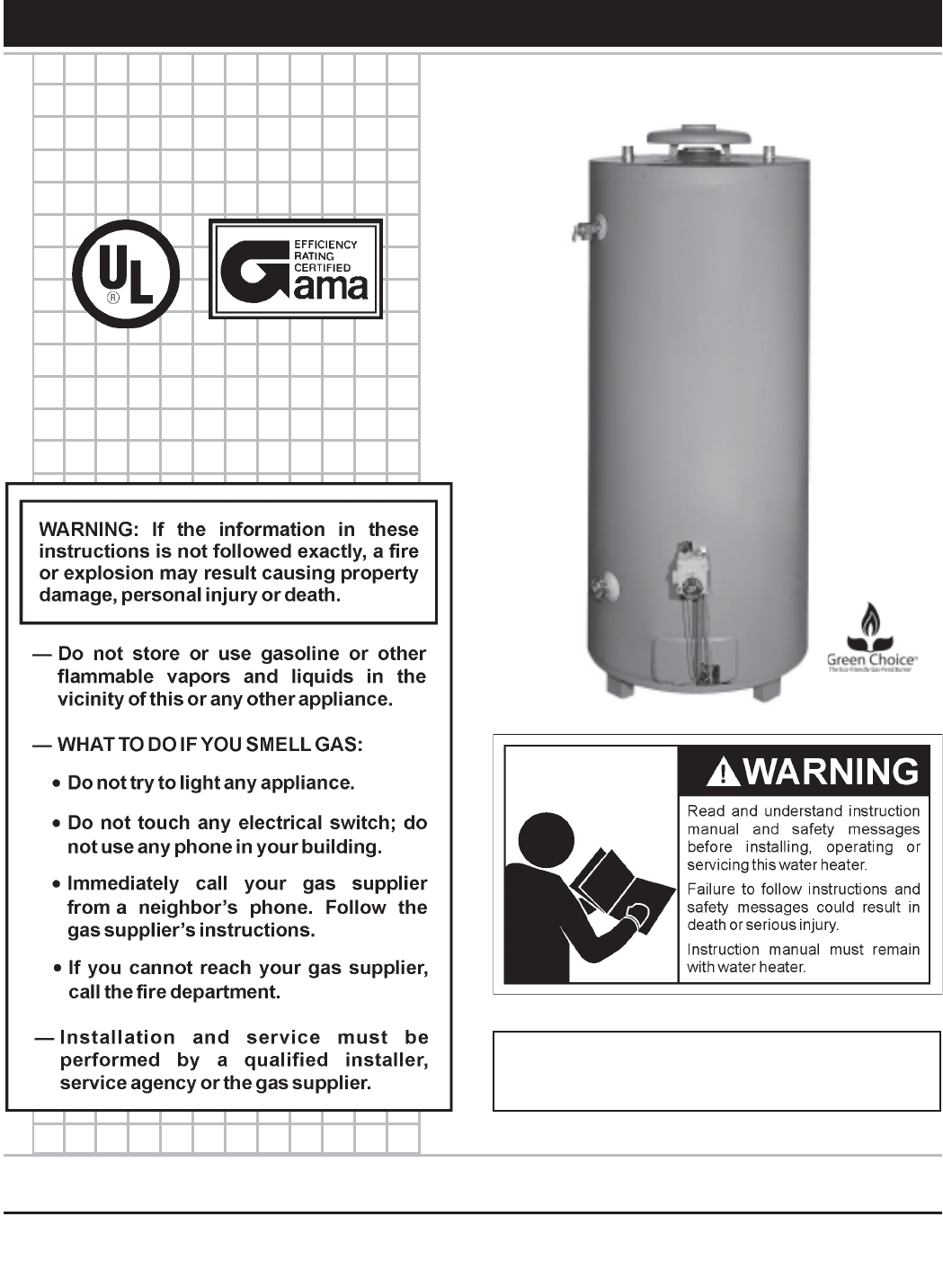
1Instruction ManualPRINTED IN THE U.S.A 1204 PART NO. 196293-002KEEP THIS MANUAL IN THE POCKET ON HEATER FOR FUTURE REFERENCEWHENEVER MAINTENANCE
10WATER PIPINGHOTTER WATER CAN SCALD:Water heaters are intended to produce hot water. Water heated to atemperature which will satisfy space heatin
11Figure 9 shows the typical attachment of the water piping to the waterheater. The water heater is equipped with 1” NPT threaded nipple(75 gallon mo
12FILLING THE WATER HEATERNever use this water heater unless it is completely full of water. Toprevent damage to the tank, the tank must be filled wi
13FIGURE 12.There must be a minimum of 6” (153 mm) clearance between singlewall vent pipe and any combustible material. Fill and seal any clearancebe
14Use pipe joint compound or teflon tape marked as being resistant to theaction of petroleum [Propane (L.P.)] gases.The appliance and its gas connecti
15FOR YOUR SAFETY READ BEFORE LIGHTINGWARNING: If you do not follow these instructions exactly, a fire orexplosion may result causing property damage,
16FOR YOUR SAFETY READ BEFORE LIGHTINGBEFORE LIGHTING: ENTIRE SYSTEM MUST BE FILLED WITH WATER AND AIR PURGED AT FAUCETS.WARNING: If you do not follow
17FOR YFOR YFOR YFOR YFOR YOUR INFORMAOUR INFORMAOUR INFORMAOUR INFORMAOUR INFORMATIONTIONTIONTIONTIONSTART UP CONDITIONSDRAFT HOOD OPERATIONCheck dra
18Because of the suddenness and amount of water, condensation watermay be diagnosed as a “tank leak”. After the water in the tank warms up(about 1-2
19VENTING SYSTEM INSPECTIONAt least once a year a visual inspection should be made of the ventingsystem. You should look for:1. Obstructions which co
2SAFE INSTSAFE INSTSAFE INSTSAFE INSTSAFE INSTALLAALLAALLAALLAALLATIONTIONTIONTIONTION, USE AND SERVICE, USE AND SERVICE, USE AND SERVICE, USE AND SER
20INSTALLED IN SUITABLE AREA: To insure sufficient ventilation andcombustion air supply, proper clearances from the water heater mustbe maintained. S
21LEAKAGE CHECKPOINTSLEAKAGE CHECKPOINTSLEAKAGE CHECKPOINTSLEAKAGE CHECKPOINTSLEAKAGE CHECKPOINTSSERVICEBefore calling for repair service, read the &q
22 Key No. Part Description1 Pipe Nipple2 Burner Tube3 Burner Head4 Thermocouple5 Pilot6 Draft Hood*7 Draft Hood Brace8 Inlet Tube9 Flue Baffle Assem
23TROUBLESHOOTING GUIDELINESTROUBLESHOOTING GUIDELINESTROUBLESHOOTING GUIDELINESTROUBLESHOOTING GUIDELINESTROUBLESHOOTING GUIDELINESThese guidelines s
3GENERAL SAFETYGENERAL SAFETYGENERAL SAFETYGENERAL SAFETYGENERAL SAFETY
4SAFE INSTALLATION, USE AND SERVICE ...2GENERAL SAFETY ...3T
5TYPICAL INSTTYPICAL INSTTYPICAL INSTTYPICAL INSTTYPICAL INSTALLAALLAALLAALLAALLATIONTIONTIONTIONTIONGET TO KNOW YOUR WATER HEATER - GAS MODELSA Vent
6TYPICAL INSTTYPICAL INSTTYPICAL INSTTYPICAL INSTTYPICAL INSTALLAALLAALLAALLAALLATIONTIONTIONTIONTIONFIGURE 2. MIXING VALVE USAGEThis applianc
7FACTS TO CONSIDER ABOUT THE LOCATIONCarefully choose an indoor location for the new water heater, becausethe placement is a very important considerat
8Minimum clearances between the water heater and combustibleconstruction are 0 inch at the sides and rear, 4” (102 mm) at the front,and 6” (153 mm) fr
9A. ALL AIR FROM INSIDE BUILDINGS: (See Figures 4 and 5)The confined space shall be provided with two permanent openingscommunicating directly with an
Related products and manuals for Water boiler State GS6 75 XRRS
 (32 pages)
(40 pages)
(22 pages)
(60 pages)
(56 pages)
(20 pages)
(20 pages)
(20 pages)
(32 pages)
(40 pages)
(22 pages)
(60 pages)
(56 pages)
(20 pages)
(20 pages)
(20 pages)
 (16 pages)
(24 pages)
(52 pages)
(24 pages)
(36 pages)
(56 pages)
(52 pages)
(40 pages)
(16 pages)
(24 pages)
(52 pages)
(24 pages)
(36 pages)
(56 pages)
(52 pages)
(40 pages)
© 2020, manymanuals.com. All rights reserved. | 1.508 s |
 Manymanuals.com
 Manymanuals.de
 Manymanuals.fr
 Manymanuals.it
 Manymanuals.pl
 Manymanuals.cz
 Manymanuals.es
 Manymanuals-pt.com
Comments to this Manuals